Platform
Our Building Blocks
The Hyperion PET detector platform provides a comprehensive set of hardware and software components to construct, scale, calibrate, and operate PET systems. While this makes the setup of a new PET scanner efficient and reliable, the platform still offers the high flexibility that you need for research and for the adaptation to specific layouts and applications.
Watch the video for a quick introduction to our PET detector platform!
The following image gives an impression how the building blocks can be combined to form a PET scanner. It also gives examples of different housings that structure and shield assemblies of building blocks to form PET detector modules. Those modules can be easily integrated into a multitude of PET scanner layouts, environments, into other imaging modalities like MRI, and for various performance requirements.
Tap on the components to find their descriptions!
Detector Stack
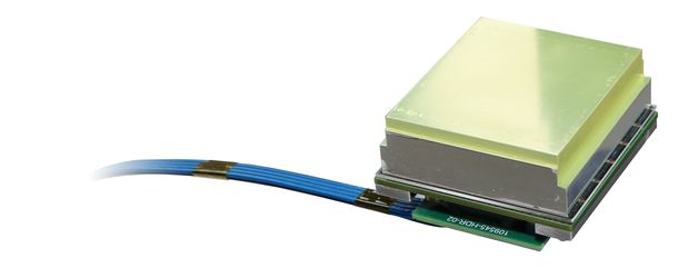
The Hyperion PET detector stack consists of multiple layers: The top layer is made of scintillation crystals which are attached to a photo sensor array being part of a so-called tile, which on the flip-side holds the read-out electronics. The bottom layer of the stack is a mechanical interface for mounting and cooling. Each detector stack is connected by a tile cable to the Singles Processing Unit (SPU) for power supply and communications. The shown picture is an example, a stack may look slightly different depending on the selected crystal, tile, and cable.
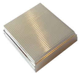
The scintillator converts incoming gamma rays into light that can be sensed by appropriate photo sensors. The topology of the scintillator needs to be tailored to the intended application. Whereas larger whole-body scanners may employ arrays made from 4 mm x 4 mm x 19 mm LYSO crystals for good timing performance, an organ-specific PET scanner typically focuses on a high spatial resolution. The Hypmed breast insert, for example, employs the shown three-layered DOI-capable scintillator made from 3425 crystals with a pitch of 1.33 mm.
Sensor Tile
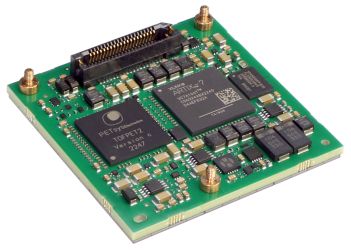
Hyperion offers a whole family of sensor tiles from which you can choose the family member that best matches your requirements. The Hyperion Visor sensor tiles realize state-of-the-art PET detector performance in an outstandingly compact form factor, with a height of 7 mm only! While the tile variants differ in selection and layout of the photo sensors, the flipside with the electronics is the same for all, employing a PETsys TOFPET2 ASIC for digitization and providing circuits for precise bias voltage control and communications. A mechanical interface is part of each tile for combined mounting and cooling.
Hyperion Visor Max

The overall detector area of our newest tile variant is 56 mm x 56 mm large. It employs Broadcom’s 6 mm MT-SiPMs in a 7 mm pitch. Each SiPM is directly connected to an exclusive ASIC channel to offer homogeneous performance. The Hyperion Visor Max offers a straight-forward detector design at a great cost-performance ratio.
Hyperion Visor HD
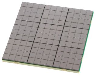
The Visor HD employs 12 x 12 of Broadcom’s 4-mm MT-Series SiPMs in a detector area of 49 mm x 49 mm. Compared to Visor Max, the SiPM density is almost three times higher, which qualifies the Visor HD for high-spatial-resolution detector designs. The 144 SiPM sensor channels are compressed for the digitization with a single 64-channel ASIC, keeping the electronics compact and energy-efficient even for this high-resolution variant.
The Visor HD is available with different compression schemes, all taking advantage of the light spread from a single event over multiple SiPMs. The choice of the compression scheme typically depends on the applied scintillation crystal design: For pixelated DOI arrays or slab detector arrays where a single slab does not cover more than half of the senor tile, we recommend our “Main Channel Compression” method. For monolithic crystals or other designs that spread events over a large portion of the sensor tile, other compression methods are more advantageous and can be designed on request.
Hyperion Visor Free
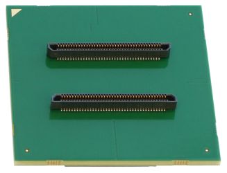
The Visor Free is a special tile particularly well suited for experiments. This tile variant comes with the same powerful electronics as our Visor Max and Visor HD, however, the sensor side of the tile lacks the SiPMs but instead offers two connectors with direct access to the 64 analog input channels. This way, various analog SiPMs, mounted on separate PCBs, can be attached to Visor Free via the two connectors. A further PCB can be stacked between tile and SiPM-board to realize arbitrary passive or even active channel compressions and signal shaping.
Visor Free is the choice for trying out new SiPMs and intermediate circuits. For a quick start, test boards with Hamamatsu Photonics and Broadcom SiPMs are available as well as compression boards with different compression schemes including such for testing row-column sum with a bread-board area that allows using optional amplifiers.
Hyperion DPC-Tile
not for new designs

Hyperion’s former fully digital sensor tile was based on the DPC-3200 sensors from Philips Digital Photon Counting (PDPC). We cannot offer it anymore since Philips discontinued the production of the DPC-3200 and any follow-up models. Our new Hyperion Visor HD is the full-fledged successor of the renowned DPC-Tile and comes with the same mechanical form factor as well as the same sensor resolution.
Tile Cable
The tile cable connects a detector stack to the main board of the electronics, a.k.a. Singles Processing Unit (SPU). Tile cables enable power supply and the transport of control, status, and read-out information with up to 1.8 Gbit/s per stack. Their length can vary between a few centimeters and several meters, giving freedom of design especially where space is rare and interference of electronics with other imaging modalities needs to be minimized. Two variants of cabling are available.
Standard

In environments with low requirements on magnetic and electromagnetic interference, off-the-shelf USB-cables can be used for flexible connections between detector tiles and main boards.
MRI compatible

These custom-made cable assemblies can be used in strong magnetic and electromagnetic fields like in the bore of an MRT. The cable has a width of 6 mm and a height of 3 mm (or 12 mm x 1.5 mm when laid-oud flat). The minimum bending radius is 3.2 mm – yet the cable is ruggedized and tolerates up to 7000 bending cycles. Cable lengths of up to 5 m were tested successfully.
Singles Processing Unit (SPU)
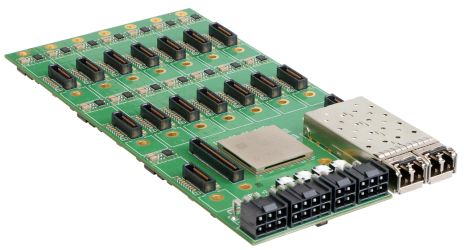
The Hyperion SPU controls up to 15 detector tiles, collects and (pre-)processes read-out data, and sends the bundled data stream via optical 10-Gigabit Ethernet to the data acquisition system. The supply voltages for each tile can be controlled individually. As such, different detector technologies are supported. Multiple SPUs can be synchronized either galvanically or optically to ensure MRI compatibility.
Communication and processing on the SPU are currently implemented either on a cost-effective XC7K160T Kintex-7 FPGA (Xilinx) or on a XC7K410T offering more processing resources. The second optical transceiver can be used to double the transmission of acquisition data up to 20 Gbit/s, or to synchronize multiple SPUs of a PET system avoiding a galvanic connection for highest MRI compatibility.
Data Acquisition and Processing Server (DAPS)
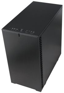
Sensor data and coincidence processing is realized in software which gives great flexibility to optimize for specific applications. The software runs on the Data Acquisition and Processing Server (DAPS) which collects the sensor data from all SPUs. The DAPS is optimized for performance: It can save the detector raw data for later processing and analysis, or directly process singles and coincidences on-line. The hardware can be tailored to actual application needs and can range from a small desktop-like computer up to a powerful server.
Control Software
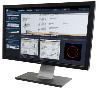
The PET system is controlled with a software offering an intuitive graphical user interface that communicates with the detector hardware, either via a direct Ethernet connection, or through the DAPS acting as a router for control and status information. The software reads the different PET scanner configurations from XML files, configures the hardware, controls it during the scans, and displays status information graphically. Whereas regular users can operate the system with a few clicks, the expert user can change every setting of the scanner and even program scripts, e.g. to automate the acquisition of a series of scans. All data is saved with additional information and log files in a database to keep all scan information together.
Data Analysis Software
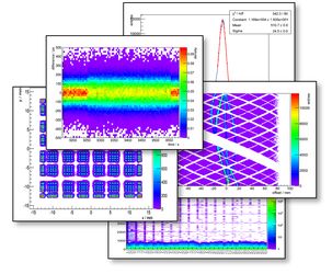
Our software package enables you to analyze in-depth raw detector data and to perform the full processing from raw sensor data to singles and coincidences. At each processing step, data can be visualized in a variety of ways. Calibration values needed to correct raw sensor data, detectors and the full PET system can be generated and applied. Data integrity of the PET system can be checked and investigated for influences of a simultaneously operated MRI scanner. The latter can be done with a high temporal resolution that allows for instance to investigate the PET data during the various stages of an MRI sequence, looking for the exact moment when the gradient or RF system are switching their fields. The software is aimed at flexibility to allow for easy implementation of new processing algorithms. It is also used to compute calibration values which are exported to the Data Acquisition and Processing Server (DAPS) to apply them in the efficient on-line processing at scan time.
